

©2000-
Website Design by DESERT WEB MARKETING LLC.


Have a Product You think we should be using


Home and Limit switches are not required but definitely have some advantages. We wired up both the home and limit switches on this project. Home switches provide a “Home” known location for the machine. This becomes a known point of reference for the machine and will allow a know start point and can be used as a restart point should something happen during the cut process. Limit switches are as the name implies switches that put limits on the machine. They stop the machine motion when it reaches a position.
Limit switches are not as critical with steppers but with servo systems they are very much needed incase of a runaway situation to keep the servo from doing damage. We are using steppers so the install of the limit switches is not required but we like the benefit of having them on the machine to prevent the motors from trying to drive past the boundaries of the machine.
Limits and homes can be installed on every axis of the machine. We choose not to install limits or homes on the Z axis. Mainly because we have found that they are not really necessary from our experiences with our CNC Plasma Systems.
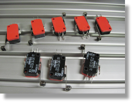
For this project we choose some switches that we had not used before. On our CNC Plasma project we choose some basic micro roller arm switches. The problem was they were a little too micro and were hard to work with. For this project we picked some large micro switches that use a feature called “snap action” Here is the info from the manufacture:
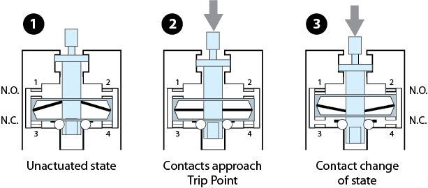
Snap Action Contacts -
In snap action contacts, the movement of the actuator applies force to an overcenter mechanism. This mechanism creates a quick change in contact state when the trip point is reached. Reversing the motion of the actuator to a given reset point causes the contacts to snap back to their original position.
Snap action contacts have different trip and reset points. The distance between the trip and reset point is called the travel to reset, hysteresis, or differential. Finite travel to reset helps to avoid multiple changes of state if the object actuating the switch is subject to vibration.
Snap action contacts ensure repeatable performance in applications that involve low speed actuators. The amount of travel of the contacts is also not dependent on the amount of travel by the actuator.
The Bladerunner manual has a section that clearly covers the configuration side of the switches in Mach3. Basically you just have to click a few boxes and enable the switches in the software.
The home switches are wire individually. The are wired in the Normally open style.
The Limit switches are wired in series in the Normally Closed Style.
We used inexpensive Bell Wire to wire them up. We used the white wire for the common and then the red for the NC or NO connection. Color does not matter as long as you understand where the connections go.
It is critical that the switches do not move at all from the position they are mounted
to allow for repeatability and accuracy. We drilled and tapped all of the mounting
locations using 4-
We also stacked the Home and Limit switch on the front side of the Y axis and the left Side of the X axis to save space. The Home contact was bent slightly forward to ensure it trips before the limit switch.
All of the wires were organized as neatly as possible and routed back to the Bladerunner controller box to make the final connections.
This operation does require opening the Bladerunner box and making a couple of simple connections. Make sure the power is off before opening the box.
Check out the photos to the left.